25+ low level and high level amplitude modulation block diagram
30 Low-level Transmitters Block diagram for a low-level AM DSBFC transmitter. A low level AM.

Sg3525 Pulse Width Modulator Datasheet Pdf Download
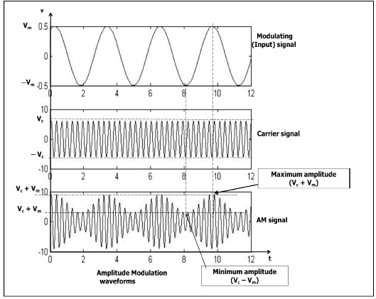
Let A max and A min be the maximum and minimum amplitudes of the modulated wave.
. A max A c. 25 points An the amplitude modulation technique see the block diagram important application of what we learned in this course in comm of cosnct 2 cos2 t mt. Low level modulation is modulating an RF source at a power level of mWs.
Message amplitude A m 025 V Vdda 5 V AGND Vdda2 25 V. 50 - A1 Amplitude modulation Figure 1 - AM with m 1 as seen on the oscilloscope A block diagram representation of eqn. 4-1 Low and High Level Transmitters There are two approaches to generating an AM signal.
Grid modulation of the output stage is the highest level of modulation employed in TV transmitters. The functional block diagram of the Amplitude Modulated AM Radio transmitter is as follows. A high level transmitter performs the modulation step last at the last or final amplifier stage in the transmitter.
Amplitude modulation is a process by which the wave signal is transmitted by modulating the amplitude of the signal. RF Carrier oscillator To generate the carrier signal. Each method has advantages and disadvantages and both are in common.
These are known as lowand high levelmodulation. Modulation demodulation class-12 1 Answer 1 vote answered Mar 14 2020 by Richa01 536k points selected Mar 15 2020 by Mohit01 Best answer Low level modulation is. Nearly perfect nonlinear resistance characteristic.
The RF crystal oscillator is most stable mechanical. Usually a crystal-controlled oscillator is. Figure 3-2 Nonlinear device used as a detector.
With Modulation Index u 25 Message signal strength is reduced keeping the carrier strength same. The block diagram of a low level AM transmitter is shown below. The amplitude modulated radio transmitter is made up of two.
2 is shown in Figure 2 below. It is called high-level modulation in TV broadcasting and anything else is then. This has to be increased to the transmission level power by amplifiers which may have to linear.
We will get the maximum amplitude of the modulated wave when cos 2 π f m t is 1. Theyre easy to identify. It is often called AM and is commonly used in transmitting a piece of.
AM message sine wave µ. Can handle high power. Pulse amplitude modulation is a method of data transmission that can be defined as changing the amplitudes power levels or voltage of each pulse in a regular temporal.
1

Circadian Curve And Terminology A Model Curve Representing A Circadian Download Scientific Diagram
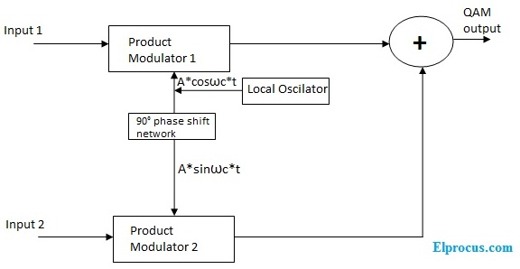
Quadrature Amplitude Modulation Block Diagram Its Working Principle
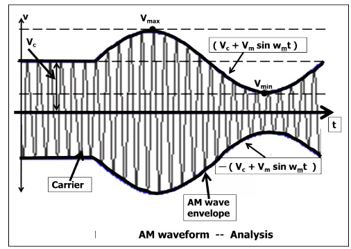
What Is Amplitude Modulation Types Advantages Disadvantages

Circuit Diagram Of Pulse Position Modulation Ppm Modulator Circuit Design Circuit Diagram Positivity

Block Diagram Of Pulse Position Modulation Ppm Circuit Design Positivity Circuit
1
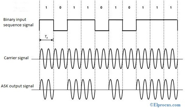
Amplitude Shift Keying Circuit Diagram Working And Its Applications

Analog To Digital Conversion Adc Analog To Digital Converter Block Diagram Digital

Low Power Mw Am Transmitter R Electronics

Circuit Design Circuit Amplitude Modulation
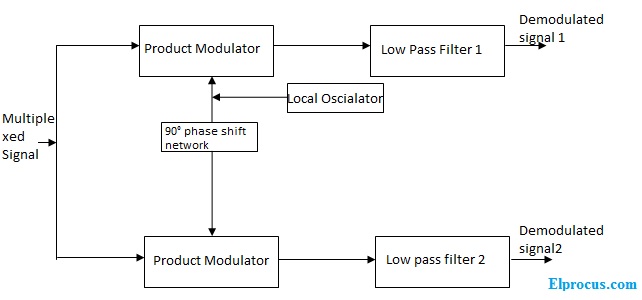
Quadrature Amplitude Modulation Block Diagram Its Working Principle

Pulse Amplitude Modulation Pam Working Types Its Applications
1
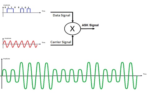
Amplitude Shift Keying Circuit Diagram Working And Its Applications
1
What Is Amplitude Modulation Types Advantages Disadvantages